When installing a DMP Panel:
- Take a note of the sticker on the panel where the cell card terminal is located. There is a temporary 5 digit code enter the menu setting on the keypad. Place the cell card in the slot on the right side of the panel. Be sure to use the plastic spacer on card so that the circuits do not short on the panel. Secure the antenna with the gold washers, lock washer and nut.
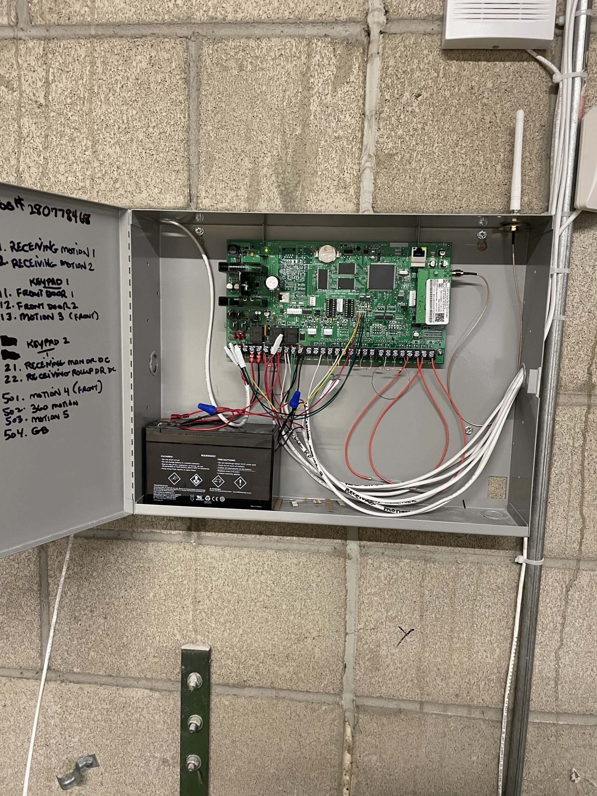
- The panel comes with resistors for the zones and 1 resistor for the bell terminal. Also on certain types of panels there are the orange colored resistors for zones 9 and 10. The bell resistor goes across both terminals in a normally open state. The positive leg of the bell cable goes to 1 terminal and the negative leg lands to the other.
- Be sure to write the CS # on the panel door and the job number.
- The 500 bus terminal is for jobs that include single zone expanders (loop system).
- The xbus terminal is for the wireless receiver for any wireless zones.
- This panel in the photo is an XR 150 series which means it only has the 500 bus terminal. Other series that are higher will have 600 bus and then 700 bus and even 800 bus included.
- Be sure to pull the tiny black jumper off and land it on 1 leg of the pins. This is your panel reset jumper so you can get into programming on the keypad.
When programming a DMP keypad:
- If dealing with more than 1 keypad, only work with 1 of them landed on the panels keypad terminals in order to program the keypads address. After programming the address for each individual keypad, excluding keypad 1, then you can land all keypad cables on the panels terminals.
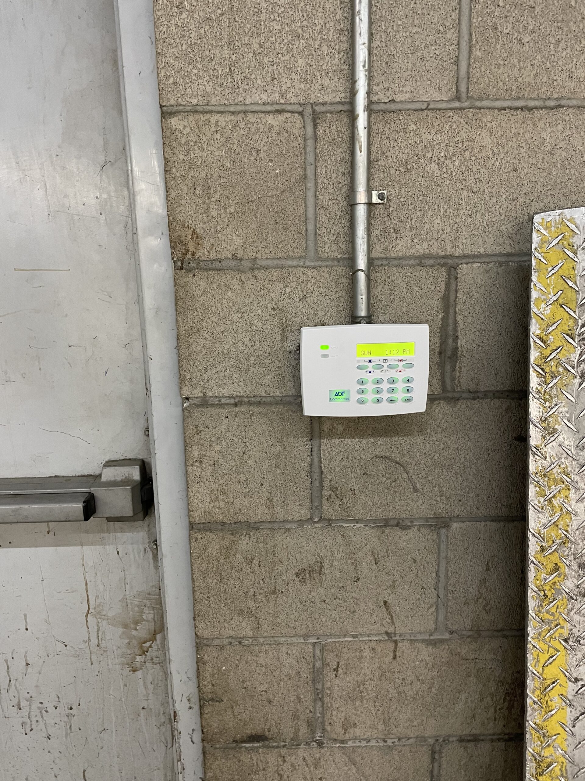
- To address a keypad, hold the bottom 2 buttons (back arrow and command key) down on the keypad until you hear a single beep then type 3577 to enter Keypad programming. Address the keypad. also be sure to turn on the police and medical for the panic keys. Hit stop on the menu screen to save settings.
- To get into the programmer section on the keypad go to the panel and reset the panel by using the jumper on both pins.
- Type 6653 to enter programming. Use command key to move forward through the menu and the back arrow to move backwards.
- Program the communication first with adding the last 5 digits of the CS number for this job. Create the paths for the cell communication. Path 1: cell, Path 2: Backup tech support will have the ip addresses and ports for each individual job. be sure to create a test time usually use 12:12am.
- Program System Reports: open and close reports set to YES, Abort reports set to YES, Zone restoral reports set to YES, Bypass reports set to YES, Ambush set to YES,
- Program System Options: choose area for system type. Hit the command key until get to House code: this will set to 10 for using wireless zones only.
- Program Area Information: create area 1 and name it.
- Program zone information: 1-8 are zones landed on the panels zone terminals. Zones landed on the keypad are number depending on the address of the keypad. (ex: keypad 1 zones would be 11-14, keypad 2 zones would be 21-24). All devices will be programmed as NT (night time) unless its an entry door (front doors and receiving doors) which would be programmed as EX (entry/exit) to allow entry time to disarm system.
- Programming wireless zone: 500-599 using the serial numbers on each device. When prompt to go to next zone click No and you will now be able enter the devices serial number.
- Programming user codes: hit the command key until you get to menu. select yes and it will prompt you to put in the 5 digit temporary code that is on the sticker at the panel where the cell card is placed. Once in menu, command over until you see user codes. you can now add, change, or delete users.
- Add user #99 Follow the prompts, active select “yes”, temp code select “no”, user code make it our 4 digit tech code, make user name “tech” and last it will ask for what profile to use, put in 99. Command and the it will state user added.
- Add the “Duress” user the same way as user #1. Using the 4 digit Duress code that we use.
- Now go to “user profile” section in the menu which is 1 section before user codes. Go to user profile #1 and select CHG for change.
- Scroll through and give this user profile the ability to disarm, arm all areas by selecting the numbers. Just make sure that this user can send signals by disarming and arming the system. Command to end and save.